Tutorials
Creating a Model from a CAD File (VIDEO) | Reference Graphics Layers and Stages | Staging Airways | Sins of Mine Air Recirculation | Introducing VentLOG Software | Gas Simulation (Advanced Version) | Fan Simulation in Ventsim | Setting Custom Icons in Ventsim | Optimising Ventsim Display Speed | Dynamic Contaminants (Advanced Version) | Advanced Mine Air Recirculation | Validating Your Ventsim Model | Auditing of a Ventsim Model | What is Mine Resistance? | Ventsim 4 Fan Curves | Photographic Textures | Creating a Basic Model (VIDEO)
Creating a Model from a CAD file (Video)
This video will teach you how to create a Ventsim model from an existing CAD file.
Reference Graphics Layers and Stages
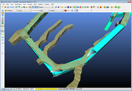
This new feature allows reference graphics objects to be assigned to primary or secondary Ventsim layers so that all or part of the graphic can be hidden depending on the type of view chosen.
Ventsim 4.1 introduced layering of reference graphics (imported CAD file graphics). Previously, reference graphics have only been static overlays onto Ventsim models that can be turned on and off. The new feature allows reference graphics objects to be assigned to primary or secondary Ventsim layers so that all or part of the graphic can be hidden depending on the type of view chosen. This allows mine plans, future stope development, voids and other 3D structures to be displayed with the corresponding Ventsim airway layer plan.
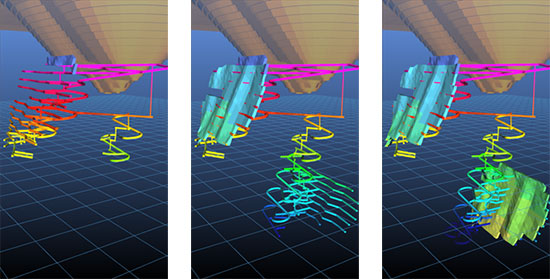
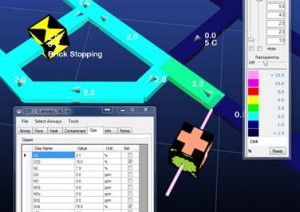
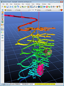
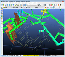
Images show both the Ventsim airway model and reference stope graphics progressing into various future stages.
In addition, references can also be assigned to STAGES, so that current or future development in the mine can be shown or hidden, depending on the stage assigned to it.
To use the new feature, select the SELECT button sub-option called > REFERENCES, and then simply click or fence around the area of reference graphics you want to change. The selection will highlight. Finally, click the EDIT button twice on the toolbar, and the REFERENCE EDIT will show, allowing changes to the layers, stages and colours of the selected graphics. The selected reference graphics elements can also be SPLIT from the existing reference graphics object to create a new object in the reference graphics list.
Staging Airways
Staging is a term representing the ability of Ventsim to create multiple versions of similar models in a single simulation file.
Ventsim Version 3+ introduces a 10 great new feature called “STAGING”. Staging is a term representing the ability of Ventsim to create multiple versions of similar models in a single simulation file. Examples of this may include creating ventilation models representing different phases or timelines of the mine design, or alternatively it could be used for representing different options and variations for a ventilation design.
How to STAGE multiple extensions of a single ventilation model
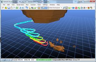
In this example, the ‘Blue Sky’ model will be used to create four models representing different periods of time. The fully worked model is available in the FILE > DEMONSTRATION > METAL MINE menu of Ventsim 3.
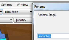
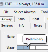
1. Firstly, create names for four (4) different stages. In this case, the names “Production”, “Pre-Production”, “Preliminary” and “Initial Development” can be entered by either selecting the STAGE list box and RIGHT CLICKING the box to change the first four list names, or by using the TOOLS > STAGING option to enter the names on a spreadsheet.
2. The final ultimate ‘base’ model can initially be made to belong to ALL four (4) stages by selecting and then EDITING all airways, and selecting the first four stages in the EDIT box. This will make the full mine model appear when any of the four stages are selected from the stage list box.
Up to 12 different stages can be developed in a single model. Each stage can ‘share’ common airways with other stages, or can have unique airways that are only valid for a particular stage or stages.
Staging is a great alternatively to creating multiple different Ventsim files that can quickly become out of date. Because staging shares common airways, then changes to shared airways on one stage will automatically occur on all other stages. In addition, every stage shares a common set of presets such as fans, resistances and friction factors.
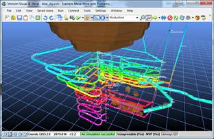
Full Mine Model – initially set to appear in all four stages
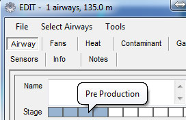
3. Now, switch to the 3rd stage (Pre-Production), and then select all airways which ONLY belong to the final stage (4). These airways DO NOT exist for stages 1, 2 and 3 and therefore must not be set to belong to these stages. Once the selected airways are deselected from stages 1, 2 and 3, press OK and they will automatically disappear from these stages.

Stage 3 – The second exhaust shaft to the right has been omitted.
4. Switch to the 2nd stage (Preliminary), and the SELECT all airways which only belong to Stage (3). Edit these airways, and deselect the stage option for Stages 1 and 2.
Stage 2 – Ramp and initial shaft included
5. Finally, switch to Stage 1 and report step 5 for Stage 1 only. In the ‘Blue Sky’ example, only the main ramp exists, therefore after editing, this should be the only airways showing for the stage.

Stage 1 – Only the initial ramp showing, with vent ducts from surface.
6. To create a Ventilation Auxiliary duct system only for STAGE 1, select the ramp airways, use the ‘Duct Builder’ function (under the ‘add’ drawing button) and construct the duct and then add a fan to the duct. Select the duct, and EDIT the airway and ensure the duct only belongs to STAGE 1 (Development). The duct will only show and simulate on the STAGE 1 model.
More examples of staging are available in the Coal Mine demonstration model in Ventsim.
Sins of Mine Air Recirculation
Recirculation can be defined as any portion of mine airflow that travels through the same area more than once. Recirculated air has a number of undesirable and possibly dangerous consequences.
For the purposes of this discussion, it is NOT the reuse of air in other parts of the mine, although this can also have undesirable consequences.
While some mines allow a limited amount of controlled recirculation, for most mines it is an undesirable and sometimes dangerous result of poor ventilation design, which is often exacerbated by poor maintenance of ventilation controls. In fact, in many countries, the use of recirculated air is strictly forbidden by mining legislation.
Recirculated air has a number of undesirable and possibly dangerous consequences:
- Buildup of heat and humidity – As air recirculates, it repeatedly picks up increasing heat from machines, rock strata and ventilation fans. Moisture and humidity is increased by ground water and mining activities.
- Build of fumes and dust – Mining activities need fresh air to clear out noxious gases and dust. Recirculated air prevents this and allows fumes and dust to accumulate.
- Recirculated blasting fumes and dust may often prevent re-entry into blasted areas for extended periods of time, delaying production and other activities.
- Gas buildup, particular in coal mines can create a dangerous environment, prone to explosion or poisoning of personnel.
Chasm Consulting has been fortunate to have had the opportunity to review many mine ventilation systems around the world. Unfortunately, in a remarkably high portion of mines, recirculation is very prevalent. In some cases, mine personnel are not even aware of it.
In response to the poor ventilation conditions caused by recirculation, a common response is to install more fans or larger fans, which can often make conditions even worse.
Mine Design Issues
The vast majority of recirculation in mines is caused by two aspects of mine ventilation design:
- Underground booster fans. Booster fans are normally designed to ‘push’ air through a mine, usually to assist surface mounted fans to circulate air into further reaches of the mine. This configuration creates a high pressure zone through the region in front of the fans. ANY connection back to the mine behind the fans (drives, declines, shafts, mined out voids and stopes) provide an opportunity for air to leak back into the mine and recirculate. Even closed doors and other ventilation control may allow for unacceptable recirculation, particularly if high pressures are present.
- Solution – Use booster fans only when necessary and limit or eliminate pathways for boosted air to re-enter the mine. If possible, place booster fans near intake or exhaust shafts to limit re-entry points. Ensure any doors or controls to prevent recirculation are of high quality and regularly maintained.
- Underground development fans are another source of recirculated air regularly encountered in mines. In many cases, the auxiliary fan consumes more air than it receives, resulting in used air being redrawn back through to feed the fan intake.
- Solution – Any free standing (or hanging) auxiliary fan MUST have more air feeding past the inlet than it consumes. As a rule of thumb, try to ensure at least 0.25m/s or more of excess air moves past the fan when running to prevent air being drawn back from the working face. Test installed fans using smoke tubes or similar to ensure air is not drawn back through the fan.
- Finally, avoid using multiple in line auxiliary fans to extend duct length, unless the duct is solid, low leakage duct and cannot draw air through gaps under negative pressure. Do not use open flexible duct feeding into downstream fans and duct, as recirculation will be significant and inevitable.
Using Ventsim Recirculation Features
Ventsim Advanced has an automatic recirculation detector (the green toolbar button). This will highlight any area of a mine which has recirculation levels above a limit defined in the settings (which can be changed in the Tools > Settings > Air Simulation section).
To determine the exact portion of recirculation, place a contamination source (smoke) in any portion of the recirculated part of the mine. Set the concentration strength to ‘100’ if not already set, and perform a ‘steady state’ contaminant simulation. If recirculation is present, some contaminant will return to the same point. For example, if a contaminant value of ’44’ is seen to return to the point of original contamination, then this indicates 44% combined recirculation of the original source.
‘Acceptable’ recirculation limits need to be determined by the individual mine and subject to local mine regulations and acceptable workplace atmospheric standards.
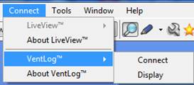
Introducing VentLOG Software
Chasm Consulting introduces a new software package to help manage recording underground measure ventilation information. VentLOG is available for separate purchase and does not require Ventsim software or licenses, and works under its own license.
VentLOG stores an unlimited amount of underground Ventilation survey data in a database format.
Underground ventilation surveys are an essential part of managing your ventilation system, and are required by law in many countries to ensure compliance with local rules and regulations.
Many mines use simple spreadsheets to record data, however this method introduce difficulties in managing data across multiple time frames and locations, and is normally difficult to analyse and compare trends and changes. In addition, using this data for making mine plans, or helping validate simulated results is time consuming and prone to duplication.
VentLOG software allows recording of dozens of different types of ventilation data, such as airflows, velocities, gases, temperatures and pressures, in a systematic database format. The data can be filtered, sorted, analysed and graphed for any location or date range.
In addition, VentLOG automatically exports results to a mine plan DXF format for easy display and inclusion in actual mine plans. Ventsim Visual software also provides a free interface into the VentLOG database, so that actual surveyed results can be displayed with simulated results for any location and date.
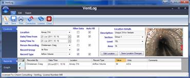
To use VentLOG software:
- The VentLOG Wizard can be used to create a new database to store your data. The wizard will guide the user through items such as database location, underground stations and authorized users. Underground stations can be established with pre-determined areas, locations coordinates, names, standard airflow directions and even pictures.
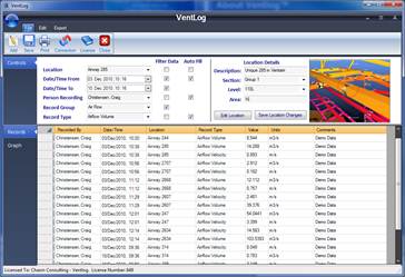
- Once locations are established, survey data can be entered against each location directly into the record sheet. The filter options can restrict the data shown to only a certain location, date range or ventilation data type.
- Each survey record required a location, ventilation data type, date and time and person recording, however the auto fill options can automatically fill the datasheet with most values, so that only the value (for example airflow) needs to be entered. All other information will automatically fill from the filter options.
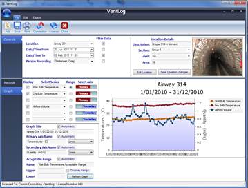
- Once data has been entered, the database can be viewed and analysed to show recorded data for any location or type. The page can be switch to ‘Graph’ mode to allow graphing of up to six types of ventilation data on up to two axes over a period of time.
- Data can be export to a DXF for importing into mine survey plans to create ventilation plans. Simply import the DXF file created into your mine survey software tool or CAD package, and the data is overlayed with your mine plan floor outlines. The position of the data and direction of the airflow arrow can be adjusted in the VentLOG locations section if they need to be fine-tuned.
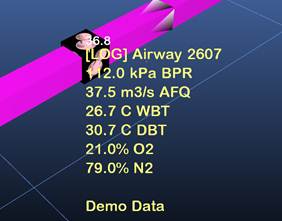
- Finally, Ventsim Visual software 2.4+ has a free connection utility that connects to the VentLOG database, and displays all surveys results within your 3D ventilation models. This is a great tool to help compare measured survey data result against simulated results, or to show historical ventilation changes.
Step 1 – Create Database
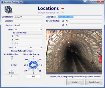
Step 2 – Establish Locations
Step 3 – Enter Data
Step 4 – Analyse or Export Data
Gas Simulation (Advanced Version)
The new Gas Simulation feature in Ventsim provides a powerful tool for simulating the spread of different gas mixtures through a mine.
Gas simulation works in a similar way to normal contaminant spread simulation. Sources of gas are established and spread through the mine, mixing at junctions with concentrations and mixtures changes depending on diluting air and other sources of gas.
The contaminant routines in Ventsim work on a simplified linear average flow, and ignore complexities such as boundaries drag issues, higher center drive velocity profiles, and potential gas densities layering issues. Such complexities introduce a number of fluid dynamic complexities which are highly dependent on geometry and airway profiles, and are outside the scope of large mine ventilation simulation analysis. In most cases, this approximation will be adequate for most mine simulation needs.
Gas concentrations in an airway are set in the EDIT box. A number of different gases can be simultaneously set, providing concentration does not exceed 100%. The remaining standard atmospheric gas concentrations (for example nitrogen) are adjusted to maintenance a 100% volumetric balance. Multiple sources of gas can be entered into different areas of the mine.
There are two methods of introducing and simulating gas to a mine model in Ventsim.
1. Set the entire airflow to a mixed concentration. All airflow travelling past this point will be set to the specified concentration. This value could be derived from measured data underground, or through theoretical analysis. All simulated airflows downstream from this point will be derived from this source. Unlike general contaminant simulation, gas passing a set source will not accumulate from upstream or recirculation sources (use Method 2 if this is required).
Method 1 – Total gas concentration in an airway
2. Inject a pure concentration of gas into an airway, and allow it to mix with the airflow in the main airway. This method relies on injecting a small concentration of airflow (gas) from a fixed flow source, and normally should be set to a ‘surface’ connection, so that the gas is injected from an external source. The gas level in this injection airway is increase to the pure gas levels (eg 75% methane, 15% CO2 etc). Downstream from the injection point, the mixture will show the diluted levels of gas. To gain a more reasonable colour scale, the legend scale may have to be renumbered to show only the concentration of interest.
Method 2 – Injection of small flows of pure gas concentration in an airway
Ventsim can optionally use the different densities of gases, and incorporate these into the natural ventilation and pressure loss calculation within the simulation. To utilize this feature, ensure that Natural Ventilation is enabled, and the Gas Density option in the Air Simulation Settings is turned on.
An area of a mine high in methane for example, may exert a significant upwards natural ventilation pressure due to the low density of the gas, and Ventsim simulation will reflect this if the option is turned on.
Gas distributions through pipes can be done is a similar way. Pipes in Ventsim can be constructed with the Ventsim ducting function, and high pressure pumps can be installed using Fixed Pressure options in Ventsim. A lesson on using this method will be included in a future tutorial.
Fan Simulation in Ventsim
Ventsim has a range of powerful facilities to simulate and estimate fan performance in a ventilation model.
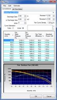
Ventsim uses a database of fan curves and settings to estimate the performance of fans in in any application underground. To ensure fans are accurately simulated, at a minimum, pressure and quantity fan curve information must be entered into the fan table (available from the Tools > Fans menu item).
To get the most out of fan simulation however, consider entering the additional optional information for more accurate results.
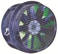
- Fan diameter or discharge area – Ventsim uses discharge size to calculate the velocity of air discharging from a fan. When using total pressure simulation, if the fan is located underground, then Ventsim assumes both fan static and velocity pressure (total pressure) is used to drive the airflow ventilation through the mine. If the fan is exhausting to the surface, Ventsim assumes the fan velocity pressure discharge is wasted to the surface atmosphere and is not used for underground ventilation.
- Fan Curve Density is an important parameter which Ventsim uses to modify fan performance at different air densities. The density in the Fan Database must be entered according to the manufactures fan curve specification NOT at the air density of the mine to be simulated. When the fan is placed in the mine ventilation simulation, Ventsim will automatically modify the fan curve to suit the simulated density.)
- Include efficiency or power curves in the fan database tables. Ventsim uses this information to accurately calculate power consumption and cost of ventilation. The information is also used to calculate heat from fans during heat simulations. Only efficiency or power data needs to be entered (not both) as Ventsim automatically calculated the other data. If the information is not available, Ventsim uses a default efficiency (set in the Settings, which may not be as accurate.
- Only Fan Static or Total Pressure need be entered (not both). It is recommended to use Fan Total Pressure where possible. Fan Total Pressure allows Ventsim to use the discharge velocity pressure to help estimate fan performance underground. If this is ignored and only fan static pressure used, fans may underperform in the simulation compared to real life.
Applying Fans in Ventsim
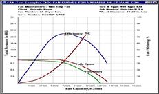
When placing a fan in a ventilation model, use the EDIT command to specify the fan configuration. Note that options are also available to adjust the fan speed (a facility available on many new variable speed fans) for increasing or decreasing performance. Pressing SIMULATE will update the simulation and show fan performance and duty points.
When assessing fan performance, ensure that the operating point of the fan does not exceed the maximum (stall) pressure. Fan performance and airflow in real terms will dramatically decrease, and fan life may be decreased. Try to design ventilation simulations well below this stall point to allow for some contingency in real life fan pressures.
Also ensure fans are not operated below the minimum (low or negated) specified fan curve pressure. While fans in real terms will still operate, power efficiency is likely to be poor, and some fan designs produce excessive vibration or blade stress. Choose a fan more suitable for this pressure duty if possible.
Setting Custom Icons in Ventsim
Custom Icons are a great way to more clearly show ventilation infrastructure icons or equipment within your ventilation model.
Older versions of Ventsim had the ability to store pictures files on a local hard drive directory (using the File > Icons menu option), and automatically map the picture to any icons in Ventsim with the same name as the picture. Unfortunately, this had some limitations: the picture had to be exactly the same name as the icon name, and the Ventsim file did not store the picture such that when the network file was loaded on another computer, the icon pictures were no longer present.
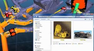
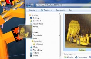
The newer versions of Ventsim (> 2.4) makes the process much easier. Standard fans, resistances and heat preset items can be changed to any picture by simply dragging a picture file on to the icon. To do this, follow these simple steps.
- Find a picture file on your hard drive in Windows Explorer.
- Drag and drop the picture file on to your Ventsim icon.
- All icons in Ventsim with the same fan or preset name will also be changed to the new picture
- The pictures are saved with the file, and can be sent to other computers without the need to copy the pictures with the file.
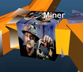
Using this option, pictures of actual ventilation fans, door, wall, regulators, and machines can be placed in your model. In addition, other non-ventilation items such as refuge bays, escape ways, workshops or even pictures of people can be placed in the models, by using a ‘dummy’ icon, such as a preset resistance name set to zero (‘0’) so it will not change the ventilation simulation.
* Note: custom icons may not work on older computers with Intel based graphics adapters, due to the limited graphics capabilities built into these cards. Any graphics hardware from NVidia, ATI, or newer Intel motherboard graphics will work fine.

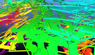
Optimizing Ventsim Display Speed
Ventsim uses the latest 3D technology to deliver unparalleled speed and animation to ventilation models.
Ensuring you have suitable graphics hardware in your computer can make using Ventsim a much more enjoyable experience. Older computers with limited graphics cards or extremely large models can slow down display of graphics. Some hints to improve speed are:
In the Tools > Settings > Graphics
- Turn on ‘Hide Text While Rotating’
- Turn off ‘Antialiasing’
- Turn on ‘Back Face Culling’
- Use Fast Text Rendering if you don’t need international characters.
Other speed up methods include:
- Turn off Text Display if not required (“T” key)
- Turn off airflow animation if not required
- Turn off node display (“N” key)
- Use Wireframe Display (“W” key) if solid graphics are not required.
To improve display quality (sometimes at the expense of speed):
- Turn on ‘Antialiasing’ if your graphics card supports it.
- If ‘stripey’ or uneven patterns appear when you zoom out, turn on ‘Back Face Culling’
- Try using a different coloured background for better contrast.
What Graphics Card do you have?
Much of Ventsim speed and performance comes down to the quality of computer hardware being used. You can check your hardware from the Help > System Info menu. Modern Graphics systems can be broadly grouped into two categories.

- Dedicated (Discrete) graphics cards produces by NVIDIA or ATI deliver by far the best performance. Even low cost versions of these graphics system (as little as $50) can make Ventsim graphics many times faster. High end Nvidia Quadro cards specified for workstation desktop and laptop computers work fine, however are not really required and will deliver little improvement over most lower cost graphics solutions.
- Intel Integrated graphics are embedded on the motherboard and deliver much slower performance. Older models such as the 45 series which are common on computers several years old (sometime specified as 4500 series) will generally deliver poor performance. Newer chipsets from Intel (such as Core i3, i5, i7 series processors) will deliver improved performance. The latest iteration of Intel Core Processors (labeled ‘Sandy Bridge’) deliver much improved performance again, equaling a low end Nvidia or ATI solution.
If you are purchasing a new computer, it is recommended that a dedicated graphics card from NVidia or ATI be specified, or one of the new generation Core i3, i5 or i7 processor computers. These computers graphics system will run the graphics in Ventsim from 500%—1000% faster than older INTEL graphics, making the program working environment much more pleasant.
These days there is very little cost premium to purchase a computer with faster graphics.
Dynamic Contaminants (Advanced Version)
Dynamic Contaminants offer a way to simulate the second-by-second spread of a contaminant through a mine. This simulation differs from the normal ‘steady state’ contaminant and gas simulations in that ventilation models can show contamination progress and concentraion at any time. Importantly, it can be dynamically changed during simulation (for example doors opened or close, fans turned off, on or reversed.)
This means that (for example) emergency procedures can be performed in the simulation at any time into the dynamic simulation to see the effect of the changes to the existing spread of the contaminants.
Contaminants are considered ‘unspecified’ in Ventsim, and can be set to any volumetric concentration. For example contaminants could be called ‘Carbon Monoxide’ and the original starting concentration set to 2000 ppm to represent explosive gases or perhaps a fire.
To set a dynamic contaminant, simply use the SMOKE button to place a contaminant and then use the EDIT function to change the concentration, type and length of time the contaminant is emitted for. This simplest dynamic form is a ‘FIXED RELEASE’ option which emits a continuous stream of contaminants at a specified concentration for a specified amount of time. Other more complex options exist to reduce concentration over time, or to simulate explosive quantities.
To release and simulate a dynamic contaminant, simply choose the Contaminant > Dynamic option and the contaminant will immediately start spreading through the mine from the source(s).
The model can be rotated at any time during simulation, and colours of contaminant levels adjusted through the color menu if required.
If a change is to be made to the circuit, the simulation can be paused at any time, and the following steps taken:
- The model is adjusted (for example a door closed, or a fan stopped or reversed).
- An airflow (and heat if required) simulation is performed to simulated the changed airflows.
- The Dynamic Contaminant simulation is resumed to show the new pathway spread of gas from the current areas.
This option can be performed multiple times during simulation, and an idea of the effect of the changes can be quickly gained.
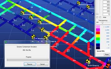
For example, if the airflow is reversed, the previous spread of contaminant may show to be ‘pushed’ back as the fresh air clears the previously contaminated areas.
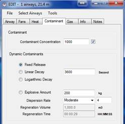
Step 1: Set the contaminant levels and release time.
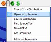
Step 2 : Start the Dynamic Contaminant routine
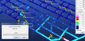
Example: The main fans are ‘reversed’ and much of the contaminated air is reversed from the mine after 20 minutes, with only ‘remnant’ contaminations remaining in slow moving airways.
Example: A dynamic contaminant of ‘1000ppm’ is released and the simulation paused after 10 minutes
Advanced Mine Air Recirculation
Recirculation can be defined as any portion of mine airflow that travels through the same location more than once.
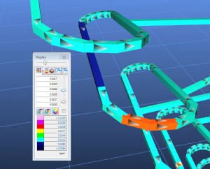
Users of Ventsim Advanced can use new recirculation simulation routines, to test and calculate recirculation through every single airway in the mine simulation model. This function provides essential information on portions of the mine that may have controlled or uncontrolled recirculation, and allows users to gauge the potential impact and consequences of such recirculation.
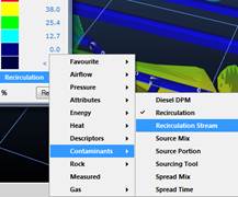
In addition, while it does not necessarily indicate how much of the air has already recirculated in other portions of the mine, there is a secondary option called ‘Recirculation Stream’ which shows the maximum amount of recirculated air present in all downstream headings.
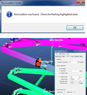
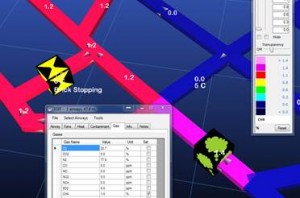
To activate the recirculation function, as before simply press the recirculation button to instantly show the results. For large models with significant recirculation, a warning may show indicating the process may take a little time to calculate.
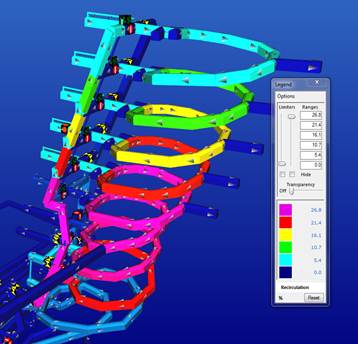
The colours will automatically change to display recirculation percentage. The alternative data display for downstream recirculation (“Recirculation Stream”) can be selected from the colour or data ‘Contaminant Menu’ group.

Recirculation showing exact % in each area. This design shows unacceptable recirculation levels in a ramp design.
Validating Your Ventsim Model
One of the most critical requirements of a Ventsim model is that it accurately represents the ventilation conditions in your mine. Without an accurate representation of current conditions, future design using the model will not be accurate and could provide misleading or incorrect results.
For this reason, validating your model with current actual ventilation data and conditions is very important.
How accurate should a Ventsim model be? There is no correct answer, but every engineer and consultant should have a target to aim for based on what the model is required for. A model that is to be used to predict future expensive infrastructure and fans should target a higher accuracy than perhaps a long term life of mine draft.
Accuracy represents the difference between modelled airflows and pressures, and the actual measured airflows and pressures. Typically most consultants will aim for around 95% accuracy in the primary airways, but this is highly dependent on the quality of data that is put into the Ventsim model and may be difficult to obtain unless a complete pressure survey is done to establish accurate resistances. For less critical applications, less the 90% may be acceptable, particularly in lower airflow areas.
In theory, if perfect input data is used within a Ventsim model, the output simulation should be also perfect. The Hardy Cross algorithm used by Ventsim ensures accuracy can be achieved (within the tolerances set for the simulation solution error). Unfortunately the airway sizes, friction factors, shock losses and fan performances are often not exactly known and can be difficult or time consuming to measure in some areas. For that reason, engineers will often use standard design sizes and default friction factors and shock losses to design a model. While not as good as measuring actual resistances with pressure surveys, this type of data will commonly still achieve 85 – 90 % accuracy, particularly if airway sizes can be more accurately validated with survey data that can help identify variation from standard design sizes.
Some tips on creating accurate models:
- Where airway sizes or resistance cannot be accurately measured, use the mine design to help create the Ventsim model, and use the actual survey data to improve the Ventsim model airway size estimation. Most mines will commonly overbreak the design size so that final airway size may be 10 – 15% larger. If this is not accommodated in the Ventsim model, the model may over predict the pressure or under predict the airflow.
- Don’t forget to consider Shock Losses, particularly at major intersection and junctions with lots of airflow. Shock Losses can commonly add 10 – 15% additional pressure requirements to a fan and must be considered. Funnily enough, engineers who do not consider over-break from design sizes, also forget to consider shock losses, and the effect somewhat cancel each other out across the model – but not always in the correct places.
- If you cannot perform a pressure / resistance survey across the mine, then at least try to measure some example resistances in main airways. These can be used to derive friction factors which can then be applied to other similar airways, and are probably better than using standard default friction factors.
- Ensure all simulation parameters and settings are accurate. This step requires a systematic audit or all information used and will be covered in more detail in a future article. Each major ventilation assumption (resistance, friction factor, airway size, fan curve, shock losses, simulation settings such as compressible flows and surface temperatures and barometric pressures) needs to be reviewed for accuracy. Most Ventsim data can be displayed in different colours so it is easy to examine an entire model for colours that are not consistent with what you would expect.
- If the mine is known to have a strong natural ventilation pressure presence, then this will need to be included in the model. While the Ventsim automatic natural ventilation option can be used, unless a very accurate heat simulation model is made of the mine this will not give the correct result. In this case, it may be best to TURN OFF automatic natural ventilation, and use FIXED PRESSURES in the surface airways to simulate known natural ventilation pressures.
Validating the Simulation versus Survey Data
The best way to validate the Ventsim simulation is to include the actual measured results of ventilation surveys as ‘Notes’ within the model. The notes can then be compared side-by-side with the simulated results, showing any discrepancies. An even easier solution is to use VentLOG software offered by Chasm Consulting that allows this to be done more easily. Ventilation survey data can be entered into the VentLOG software, and automatically overlayed on the Ventsim model.
In addition, mine survey topography can be imported as a reference and overlaid on the Ventsim model design. This will show discrepancies in design sizes and airway locations that may warrant further investigation.
Finally...
Don’t always expect the Ventsim model to exactly match the underground ventilation survey data. Often the survey data itself may have errors in measurement – it is common to gets errors of up to +/- 10% in anemometer surveys of airflow. At other times, equipment moving about, doors opening or shutting, and other temporary mine disturbances can effect airflow measurements.
If the model still gives very different results from actual measurements, don’t be tempted to blame the software or force the software to give correct answers by artificially changing or fixing settings. Provided the simulation is performing without errors or warnings, it is almost certainly simply returning the results of the input data placed within the model. Work backwards from the main airflows to the surface and try to discover the discrepancy between the data put into the model (such as airway sizes, frictions factors, regulators or doors, fans etc), and the actual data of the mine. Some parts of the mine may require a physical inspection – is the fan running? Has the drive or airway been filled with backfill or other blockages? Is the door or regulator open or close?
More often than not, a major factor or item has been missed in the model simulation, and once resolved the simulation will perform as expected.
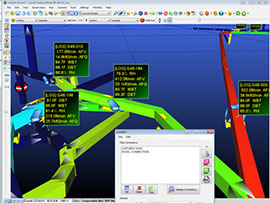
Auditing of a Ventsim Model
An important in part of creating ventilation models in Ventsim is to check or audit the model before final release or use. A ventilation model may consist of thousands of airways each with dozens of different attributes. If an attribute such as a friction factor or airway size is incorrect or inconsistent with similar airways, this can create a string of problems in the model resulting in inaccurate airflow and pressures.
Often, these problems are inadvertently included in models without the full knowledge of the user, particularly when the model or parts of the model may have been done by someone else. A system to inspect for common inaccuracies is therefore an essential part of any design process.
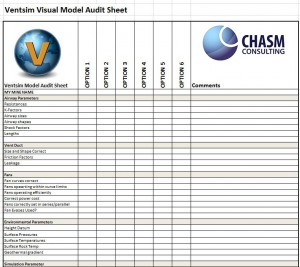
A simple system is to create a list in Excel of common items you need to check to assist with model validity. This creates a formalised way of auditing model parameters that may have been incorrectly inputted or forgotten about.
Airway Attributes
Create a list of important attributes that influence airway resistance. Airway resistance is the single biggest cause of model inaccuracies. Common attributes include (if not using directly measured resistances)
- Friction Factors
- Airway Size and Area
- Shock Factors
If measured resistances are being used, Linear Resistance is a good check.
The easiest way to check attributes is to use the attribute COLOURS to display variations on screen. Airways that are inexplicably different in colour than other airways are easy to spot, and the cause of the changed attribute can be investigated. The example below shows changes in friction factor that require further investigation.
Fans
Incorrect Fan Curves are another source of inaccurate models. They should always be checked for accuracy and authenticity.
- Check the fan curve against the manufacturers fan sheet.
- Ensure the correct pressure type is specified for the curve (Fan Total or Static Pressure) and that the simulation matches the fan curve.
- Ensure the blade setting for the fan curve in Ventsim matches the blade setting of the fan actually being used in the mine.
- Ensure the fan curve density matches the specification in the manufactures fan sheet, and the model air density is set correctly in the Settings.
- Fixed Flows are not a good idea in a final model. Only use fix flows to represent variable regulators if possible – check these with the “Restrict Only” option to allow the simulation to report problems.
Heat and Moisture
Thermodynamic simulation can be a complex modelling process, and for good accuracy requires many checks. Some of the more important ones are: Simulation > Environment. Make sure the following global items are checked:
- Surface temperatures
- Rock parameters and geothermal gradients.
- Wetness Fractions (specify this for each airway if the mine wetness is variable)
In the underground environment, the following factors should also be checked for each airway. Again, Colouring by Heat Attribute is a good way to examine for variations.
- Exposure Age – this is critical for accurate heat flow from rock strata – newer exposed airways are more critical to get right than ones that have been exposed for many years.
- Equipment Heat – Ensure the heat specified for machines is the average utilised heat output, not the maximum output. A common mistake is to include maximum engine power from diesel machine – this must be the average output and can be better estimated with the fuel consumption calculator in Ventsim.
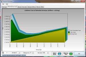
Financial Analysis
Require the accurate estimation of power costs, mining costs and airway useful life. If these factors are not correctly input, size optimisation recommendations in Ventsim will not be correct. Use the Mining Cost Calculator in the TOOLS menu for more accurate mining cost factors if you are using the QUICK or GLOBAL optimisation methods.
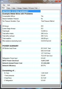
Simulation Parameters
Finally, the Simulation Parameters should be checked for the type of simulation required. The RUN > SUMMARY sheet provides an overview of some of these.
- Airflow Compressibility (normally turn on, unless validating against a Ventsim Classic or VnetPC model)
- Airflow Natural Ventiltion (normally turn off, unless an accurate heat simulation model has been done)
- Simulation Accuracy – normally set to BALANCED for general use, or HIGH if simulation for final reports. This will force the simulation to achieve a higher level of convergence (at the expense of greater simulation time)
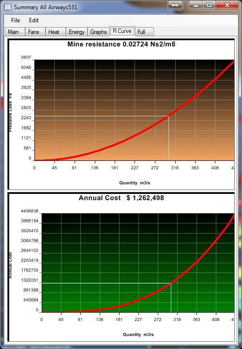
What is Mine Resistance?
We often get asked by customers why the mine resistance of their models keeps changing in their Ventsim Summary when they change their model airflow. Mine Resistance is the combined total of the resistance of all air moving through the mine, and is a useful figure to know, because it can be combined with Atkinsons turbulent flow pressure equation P=RQ2 to assist in calculating how much additional (or reduced) pressure may be require to achieve a certain volume flow of air through a mine.
Because resistance is simply a function of airways size, length, friction factor and shock loss, you would think therefore mine resistance would be combined sum of all the parallel and series airways, and would be independent of airflow changes through the mine. However, airflow distribution which is altered by fans unevenly in different parts of the mine WILL AFFECT Mine Resistance in the same way as using regulators (ie additional resistance) to alter airflow distribution.
Consider two separate cases. A mine with a single entry and exit is adjusted for flow. If the airflow is doubled through the mine, and as expected the overall pressure will be expected to increase by a factor of four (4).
Now consider a case with a single entry, but two (2) exhausts. If we were to double the overall airflow in this mine by only mounting additional fans on one of the exhaust routes, we would require a much greater additional pressure than allowing the air to flow evenly through both exhausts.
Effectively we have increased our mine resistance because we have changed the relative portions of airflow that can travel through each airway! The same net effect could be achieved by adding regulators to parts of the mine which would similarly change mine resistance.
In summary, Mine Resistance will only remain the same if the changed airflow proportions remain consistent through the mine. If we increase or decrease airflow through one part of the mine and not the other (with either fans or regulators), we also change the overall mine resistance.
Ventsim 4 Fan Curves
The tedious job of accurately entering fan curve data has been solved. Ventsim 4 introduces fan curve digitizing, where actual fan curve data sheets can be imported into Ventsim and quickly entered into the Ventsim fan database.
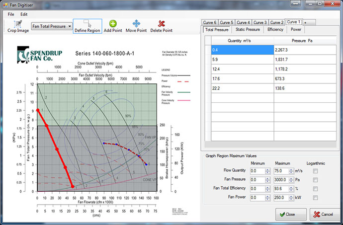
Fan curve files (either PDF documents or scanned pictures) can be dropped into the Ventsim fan database form. Users can then convert and import a range of fan blade curves into Ventsim within minutes. Follow these steps:
- Once the fan data sheet has been dropped into the fan digitiser, DEFINE REGION allows the user to highlight a box around the graph portion on the sheet. If multiple graphs are present on the sheet (for other curve data such as power), then regions can be separately defined for each graph.
- The minimum and maximum value for each graph region defined is then entered in the lower right corner.
- The ADD POINT function allows the mouse to be used to click along the fan curve lines, tracing the curves. Points are digitised and automatically entered into the fan database. Switch to different data types if other fan curve components such as power. (HINT: Maximising this form helps make the graph regions bigger on the screen)
- Additional fan curve variations (such as different blade angles) can be added by clicking the ‘+’ symbol at the top of the data grid spreadsheet. Rename each curve if required by right-clicking on the fan variation name.
- When finished, press OK, and all the fans will be available to now use in your Ventsim models.
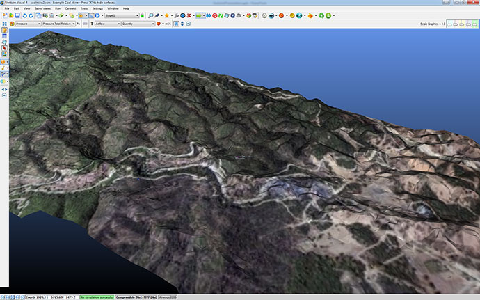
Photographic Textures
Ventsim 4 introduces photographic texturing, a process where pictures can be overlaid across 3D reference surfaces previously imported into Ventsim.
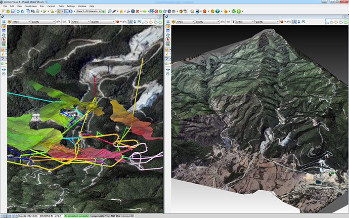
Texturing allow photorealistic visualisation of things like surface topography, where both the 3D surface graphics and photographic information can be used to show surface features. Photographic texturing can help with appropriately positioning surface ventilation infrastructure (such as shafts or portals) and can visually assist in presentation by showing where underground mine infrastructure is located in comparison with surface features.
Photographic texturing is easy to do in Ventsim 4. Follow these steps.
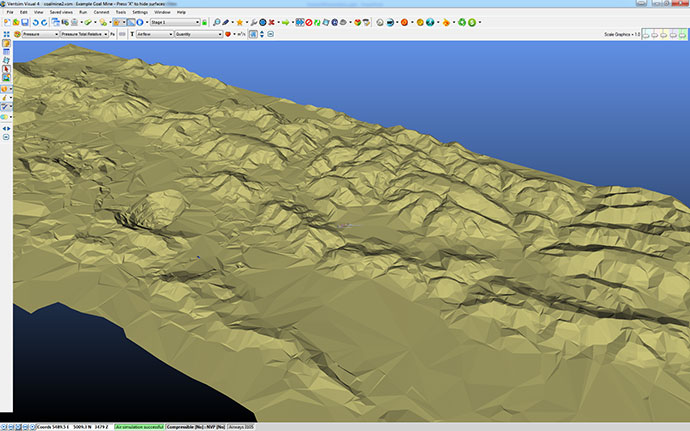
1. Import your 3D surface as a reference into Ventsim from a suitable CAD or mine planning package.
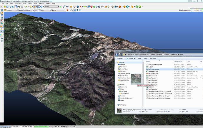
2. Drag and drop a photo file (Ventsim supports most formats including JPG, PNG, BMP etc) onto the reference surface in Ventsim.
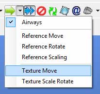
3. The photo is unlikely to be in the correct position in relation to the 3D reference surface, so it will need to be moved and probably scaled and rotated. Use the Ventsim MOVE > Texture Move button.
- Drag the picture texture across the 3D reference until a known photographic point aligns with a known 3D reference point. You can also click once to exactly define the coordinates if you wish.
- Centre the screen and the Ventsim view point of focus exactly on the known point. Use the middle mouse button option to do this by clicking on the known point.
- Finally use the Texture Scale Rotate menu button option (shown above also) to click and drag another known point on the photograph to the correct location on the 3D reference surface. The photo will automatically dynamically rotate and stretch to this location.
That’s it! Your photographic texture is now displayed and aligned correctly in 3D.
Creating a Basic Model (Video)
This video will teach you how to use Ventsim to create basic ventilation models and run simple simulations.